By Mike Moore
I hope this will make rigging biplane models easier for anyone interested. Please understand, what I’ve illustrated here isn’t THE way, or even the BEST way to rig a model of a biplane. It is however MY way, and it works well for me. It may for you as well. At least I hope so.
The following diagram explains the different type of structural rigging found on an aircraft and its specific function:
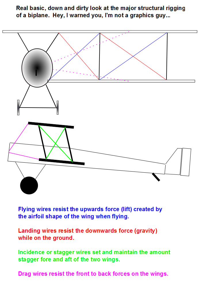
Rigging Line
You’ll want to note that I only rig with monofilament line such as fly fishing line and invisible thread. I find this medium the easiest and most realistic. As for realism, you’ll find that once your rigging is pulled taught, it serves exactly the same function the rigging does on the real thing...it makes the whole structure more rigid. Also, like the real thing, if you’ve managed to assemble something like the upper wing or under carriage a little cockeyed, you’ll find that by pulling the appropriate line tighter than it’s counterpart, you can often pull the offending part back into alignment.
I use different sizes of line depending on the scale of the model, and the use of the line on the real plane. For the few 1/72 biplanes I’ve built, I’ve just used a standard .004” Invisible Thread which can be picked up in most any good craft, sewing and quilting shops, and can even be found in many grocery stores, at least in the US. If you have the patience, and can find it, you can get monofilament in .002” size from some fly fishing shops. I just haven’t bothered.
For 1/48 scale, I typically also use the Invisible Thread for both the structural rigging and the control lines. However, for 1⁄2 scale, I will use different sizes of lines for the control lines and the structural wires. For an aircraft with wire structural lines, like German aircraft, I’ll use .006” line for those wires, and .004 for the control lines as they were under less load and therefore smaller than the structural lines.
British aircraft of course introduce another level of complexity. First off, they had double flying wires (the wires that support the wings in flight. They are the diagonal wires that run from the lower wing, inboard to the upper wing outboard). Second, 90% of the time the structural wires were actually extruded rods know as RAF Wire with an airfoil shape rather than the simpler round wire cable. The RAF wires didn’t use turnbuckles as such, but rather the ends of the wires were rounded off and threaded. The ends were then threaded onto nuts built into short rigging terminals at each end of the wire. There are photo etch RAF wires and terminals available in 1/32 scale from RB Productions. I have some, I just haven’t had the guts to use them yet. See the pictures for examples of double flying wires and the RAF wire terminals. Instead, I’ve used slightly oversized monofilament, either .008” or .009”. They aren’t noticeably oversize to me, and they probably replicate the RAF wires better than a more scale .006” or .007’ line would. For the control lines, I tend to use either .004” or .005” line.
Turnbuckles
A popular and very good material for simulating turnbuckles is brass or nickel tube. Albion Alloys makes a variety of tube sizes, the most useful for rigging are probably the .3, .4 and .5 mm diameter sizes. While the brass tube is pretty easy to cut with a hobby knife, the nickel is easier.
However, another modeler on-line (and I’m sorry, I can’t remember who) mentioned a product called Polyamide tubing. This stuff is primarily used in lab applications and is available in sizes down to seemingly hair size and is still hollow! It is also very easy to cut with the tip of a hobby knife, much easier even than nickel tube. While not completely rigid, in short sections, it will hold an absolutely straight length. I honestly don’t know what size I’ve used for 1/48 rigging, but with my most recent WWI completion, the 1/32 scale Wingnut Wings Fe2b Early, I used tubing with an inside diameter of .0201” and an outside diameter of .0221” (note these are imperial units, not metric).
Polyamide tubing is available at Amazon Supply.
I generally make turnbuckles 4-6 scale inches long.
Wire
I often make wire loops for attachment points. You can of course, buy them from Bob’s Buckles, but in all honesty, with a cheap home made tool, they can be spun in about 3 seconds each. I use some small copper wire from fly fishing suppliers. I don’t know what the size or gauge is, but it’s labeled small and x-small.
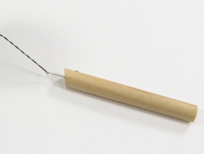
That home made tool? Here it is, a short piece of dowel, with some small steel wire with a hook set into the end. Fold over a piece of wire over the hook, pinch the ends with one hand, and spin the dowel in the other. Presto chango... a little wire loop.
A couple more notes on rigging. Make sure you think about things. You can pull a line all the way through a hole drilled into a wing, but you can’t pull the other end through a hole in the fuselage. So make sure you start the line by gluing it into the fuselage, and then you can pull it tight through the wing. And work “inside to outside”, meaning if you have a wing with two sets of struts on one wing (double bay) rig the cross bracing between the struts first and then work on the flying and landing wires. If you have double flying wires, rig the inside one before the outside. And remember no to pull lines too tight. Plastic struts bend. If you pull the rigging too tight, you’ll bend the struts. You want the lines just tight enough that they don’t’ sag. If they loosen up later, you can tighten them up by carefully applying heat. But be careful. Too much heat, or getting the heat too close to the rigging line and you’ll melt the line. Go ahead, ask me how I know...
So, without more boring stuff, on to the pictures!
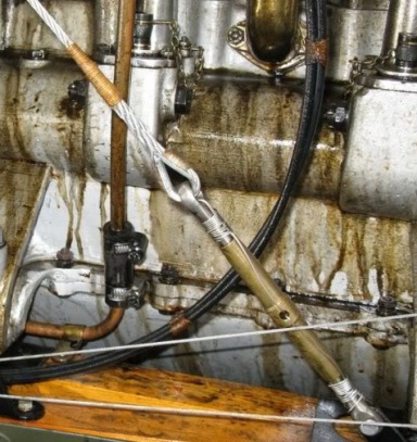
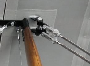
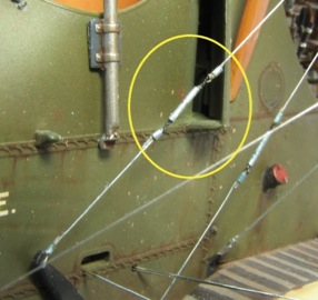
British RAF wires and the terminals they thread into. Note the double flying wires in the picture on the left.
And here’s that custom, home made wire loop spinner!
Shown in diagram 1 below is the simplest Turnbuckle method I use. It looks a bit plain In 1:32, but looks quite Nice in 1:48. I use this technique and short sections of tubing to replicate the rigging terminals for RAF wire.
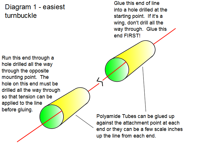
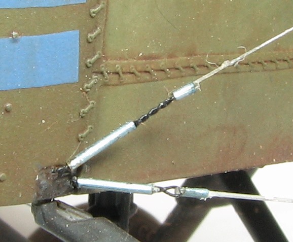
Diagram 2 shows another pretty simple method. I find it very useful when I need to attach the end of a wire to something I can’t pull the line through. Pulling the line through the loop allows tension to be pulled on the line before gluing.
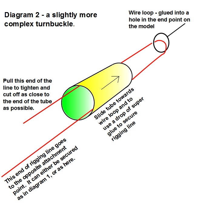
Diagram 3 is a slightly more complex variation on the turnbuckle shown in diagram 2. It has a bit more realistic appearance.
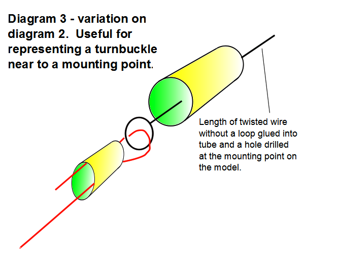
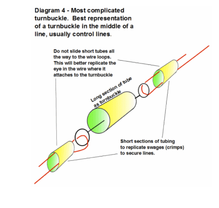
Diagram 4 shows the most complex turnbuckle I do. Many aircraft have turnbuckles in the middle of a control line. This really isn’t any harder to do than those diagrams 2 & 3, just more parts to be hooked together. One note is that the small tubes I use as the Swages were rarely present. The loops for the wire were Normally spliced into the Wire. I haven’t figured out How to really replicate a Wire splice in mono-filament!
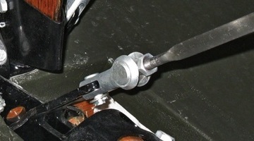
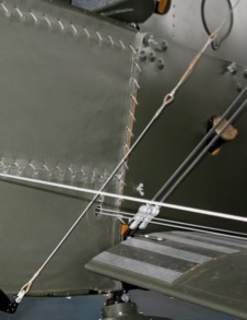
Floating turnbuckle on a model and actual aircraft
Spliced Loop